

Resources
Tolerance Guide
ISO 2768 general tolerance tables plus the process-reachable tolerance guide for CNC, casting, additive and sheet-metal processes.
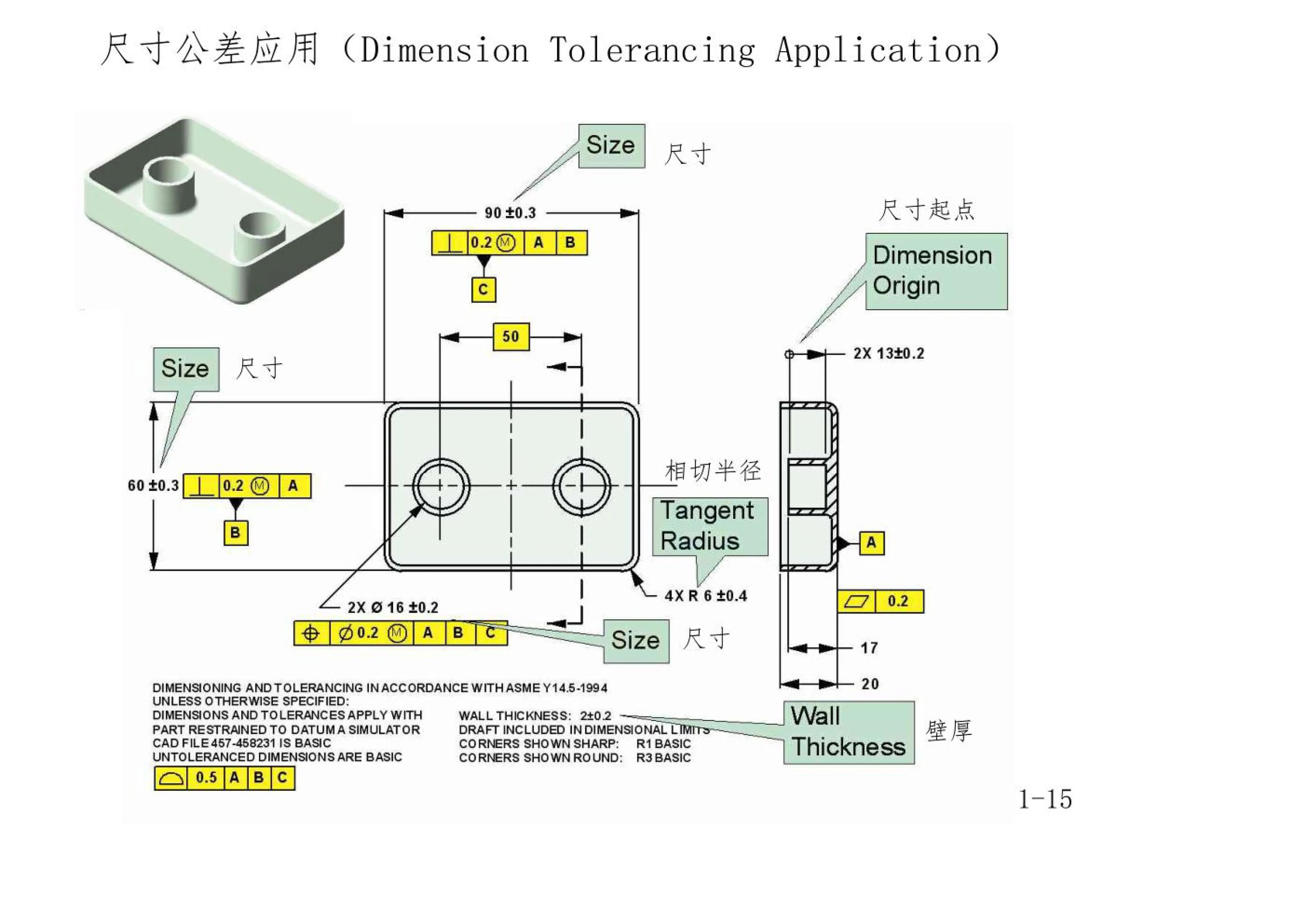
Define the dimensions that matter to fit, function and assembly.
Tolerances define the acceptable variation in a part’s dimensions and geometry. The appropriate tolerance depends on the manufacturing process, material, part size, feature geometry and finishing requirements.
Mark critical dimensions on your drawing. Maker-1 will review their feasibility and confirm the applicable requirements in the quotation and approved manufacturing documentation.
Tolerance Considerations by Process
| Process | What Affects Accuracy | What to Specify |
|---|---|---|
| CNC Machining | Part size, tool access, wall stiffness, workholding and material stability. | Part size, tool access, wall stiffness, workholding and material stability. |
| Sheet Metal Fabrication | Sheet thickness variation, cutting, bend radius, springback and forming sequence. | Formed dimensions, bend angles, assembly interfaces and hole locations. |
| Resin 3D Printing | Material, build orientation, supports and post-curing. | Mating features, inspection dimensions and acceptable support locations. |
| Metal 3D Printing | Build orientation, thermal distortion, support removal and finishing. | Critical interfaces and surfaces requiring secondary machining. |
| Vacuum Casting | Resin shrinkage, part geometry, mold condition and curing. | Assembly dimensions, cosmetic surfaces and acceptable variation. |
| Surface Finishing | Coating buildup, material removal and masking. | Whether dimensions apply before or after finishing, and which areas require masking. |
Agree on Requirements Before Manufacturing
Specify the applicable general tolerance standard and class on your drawing, where required. Any conflict between the drawing, CAD model and quotation should be resolved before production. For critical features, agree on the inspection method, inspection condition and reporting requirements before order confirmation.