

Resources
Design for Manufacturing Guidelines
DFM guidelines covering wall thickness, radii, hole sizes and undercuts, with illustrative diagrams to help you design for manufacturability.
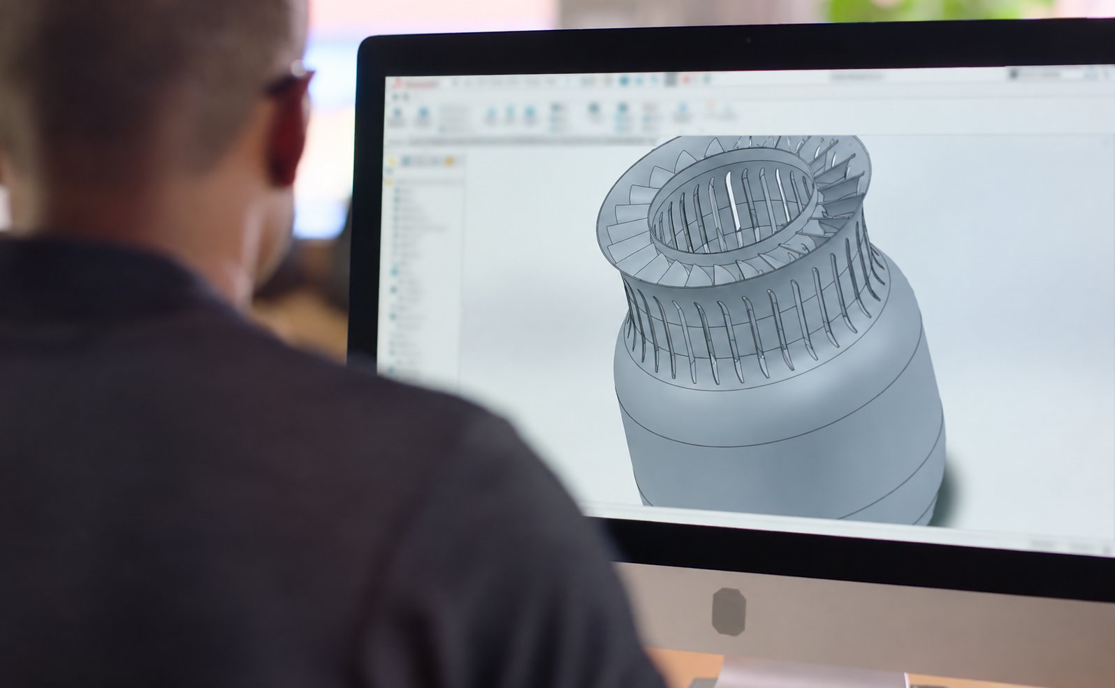
Prepare your design for machining, printing, casting and sheet metal fabrication.
Small design changes can improve manufacturability, simplify assembly and reduce unnecessary cost. Use these guidelines when preparing prototypes and low-volume production parts.
Final recommendations depend on your material, geometry, quantity and functional requirements. Submit your design for a project-specific DFM review.
1. CNC Machining
- Allow tool access to pockets, holes and machined surfaces.
- Add internal corner radii that are compatible with the cutting tool.
- Avoid unnecessarily deep, narrow pockets and slender features.
- Use standard drill sizes and thread specifications where practical.
- Identify thin walls and areas that may deform during machining or clamping.
- Apply tight tolerances only where they are needed for function or assembly.
2. Sheet Metal Fabrication
- Specify the material grade, temper and nominal sheet thickness.
- Use consistent bend radii where practical and allow space for forming tools.
- Keep holes, slots and hardware clear of bend-affected areas.
- Include bend relief where needed to reduce tearing or distortion.
- Identify formed dimensions and the surfaces used for assembly alignment.
- Provide access for fasteners, welding and assembly tools.
- Identify threads, grounding points and mating surfaces that need coating masks.
Holes Near Bends
Holes close to a bend may distort during forming. Depending on the design, the manufacturing sequence may need to include drilling or machining after bending. Specify the required hole size and position; the production method should be agreed during DFM review.
3. Vacuum Casting
- Use reasonably consistent wall sections where practical.
- Identify undercuts and features that may complicate demolding.
- Agree on parting lines and gate locations, especially on visible surfaces.
- Specify inserts, flexible sections, color and transparency requirements.
- Review assembly fits against the selected resin and expected shrinkage.
- Approve the sample’s appearance and fit before proceeding with the agreed batch.
4. 3D Printing
- Specify whether the part is intended for appearance review, fit checking or functional testing.
- Identify cosmetic surfaces and mating features before selecting build orientation.
- Allow access for support removal and post-processing.
- For hollow parts, provide suitable access for draining resin or removing powder, as applicable.
- Avoid enclosed cavities that cannot be adequately cleaned.
- Discuss thin walls, small details and precision interfaces before printing.
- Allow for secondary machining where critical fits require it.
5. Surface Finishing and Assembly
- Mark cosmetic surfaces and acceptable locations for witness marks.
- Specify the finish type, color reference, texture and gloss requirements.
- Identify areas that must remain uncoated.
- Consider finish thickness at holes, threads and mating interfaces.
- Provide an assembly drawing and bill of materials when multiple parts are supplied together.